
Last week, while waiting for something else to finish, I decided to wire up my 4th axis. That was easy enough because the wires matched colors on both sides. Plus, it is only 4 wires. Once connected, I used my MPG to step the motor and it turned while making a terrible noise. But it turned.
This weekend I decided to do the math needed as well as the research to get this thing going. I have included links to resources I used as well as a google sheet that will allow you to calculate the settings needed for the Mach 3 motor tuning page. The acceleration is just guesswork at this point. But gives a rough estimate of settings to try out. You can work with the actual hardware and the sounds it starts making to determine a better setting for your setup. The velocity settings are not 100% either, but are closer to the actual settings than not.
Math:
Depending on your stepper driver, gear ratio and microstepping settings and stepper motor amperage.
Mine:
Stepper is a Chinese NEMA23 rated at 3 amps
Gear ratio 100:1
Microstepping setting: 10
Controller used: CNCRP stepper driver which is a leadshine stepper controller, or a clone. Here is the link to the manual for the leadshine controller. http://www.leadshineusa.com/UploadFile/Down/DM556m.pdf
Degrees per step = 1.8
Steps per one revolution = 200 (360/1.8=200 )
Microstep resolution = 10
Steps per revolution with microstepping = 2000 (200*10=2,000) steps per 1 revolution, multiplied by microstep resolution.
Gear ratio = 100:1
Steps per degree = 555.5556 (10100/1.8=555.5556) Microstep resolutionGear ratio/Degrees per step of actual stepper
The steps per degree is what you need to enter into Mach 3 to control correctly. Next is to tune the motor for the correct movement. I had to fiddle with this to get the reaction I expected. Velocity and Acceleration values are not exact, at least I cannot find a way of calculating the exact ones needed. But these values work well for my setup.
Velocity = Mach 3 screen says inches or millimeters per minute(Actually degrees per minute). If set to 1, that would mean that the axis would rotate 1 degree every minute. This means that 1 full rotation would take 360 minutes.
Acceleration = Mach 3 screen says inches or millimeters per second / per second(actually degrees per second per second) This means that if I wanted to accelerate to full speed and if I set acceleration to 1, the axis would move to full speed by increasing the speed every second by 1 inch (degree) per second. So if moving 360 inches(degrees) it would take 360 seconds to get to full speed.
So if you were to go with 1 as velocity and 1 as acceleration, the speed would ultimately be the same and you would take 360 minutes to get to 1 rotation.
If we went with 360 as velocity and 1 as acceleration, then it would take 1 second to get to full speed and 1 minute to rotate 1 time. Because at step 1 it is moving at 1 degree per second and since we are trying to get to 360 degrees in 60 seconds, 1 degree per second brings us there. But we most likely want to go much faster than that.
Calculate the settings needed for the A axis to properly rotate within Mach 3. I created this little calculator to get you going. The calculated Steps per degree is exact. The other two are there for reference and to give you something to start playing with in mach. Once you find the right settings for your machine, by playing with the values until it works the way you see fit, Enter them into the Mach 3 motor Tuning A axis Page.
If the embedded spreadsheet does not work for you, you might be on a phone. I cannot get it editable on the phone for some reason. Options are limited for the embed URL options. So here is a link to the shared version on drive. Rotary Calculator
If using microstepping, make sure that the driver is set correctly. The driver I use is the default from cncrp, but they said to reference the manual of the leadshine driver. http://www.leadshineusa.com/productdetail.aspx?type=products&category=stepper- products&producttype=stepper- drives&series=DM&model=DM556
According to the sheet, to drive this specific stepper that is on my setup, I had to change the amperage to the closest supported on the driver. The rated amperage is 3 on the stepper, the closest setting on the driver is 3.2Amps. However, I am adding a fan/heat sink to lengthen the life of the stepper. I assume it will go earlier, but they are cheap.
The driver came without the microstepping set. This threw me off during calculations because the output never aligned and then I realized that sending G0 A36 caused it to rotate one full 360. After finding the manual for the stepper driver, I was able to figure out that the microstepping was not enabled. Makes perfect sense after the fact.
If you have a similar setup of needing 3Amps and 10 microsteps from the driver, your settings should be this on the dip switches.
| 1 | 2 | 3 | 4 | 5 | 6 | 7 | 8 |
|---|---|---|---|---|---|---|---|
| ON | ON | OFF | OFF | ON | ON | OFF |
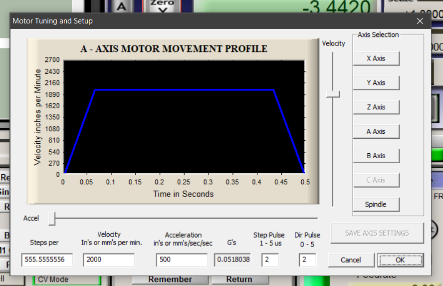
Enter the calculated Steps per, Velocity and Acceleration into the A axis settings in the Mach 3 motor tuning page. Do not forget to Save axis settings.
Once you enter the correct settings you can rotate the axis in mach. Just enter G0 A360 and watch it rotate one full time. Here is a video of mine. Terrible, shaky but you get the point.
A quick video of my rotary axis turning 360 degrees after finally getting the settings correct.
UPDATE!
I just posted this in another blog post, but wanted to add this step in so you were not confused later on.
You will need to open config - - ToolPath Configuration and then enable “Use radius for feedrate” and “A- Rotations Enable” before you will get usable speeds on toolpaths you post process. Then go to the settings page and enter 0.0001 as the Rotation Radius. Or possible enter your stock radius. This compensates the speed for distance from Z zero position. I have been raising the z axis .2 above the stock and running the code from there, it compensates when using the .0001 entry, have not tested actual radius yet. I set Z 0 as the center for rotation.
Fusion 360 Post Processor:
If using the post processor from CNCRouterParts, then the A axis is not configured by default. I posted on the CNCZone forums about needing help with modifying the post processor and someone wrote back with this short tip here. Open the post processor, I opened it while within the fusion CAM section, by going to the post process action. To do it, you will need to have a setup defined. If the path is not generated, it will throw a warning about wanting to do it anyway. Accept the warning and then when the post processor page opens, choose your post processor if it is not already chosen and then click on “open config”. It should open in the brackets code editor.
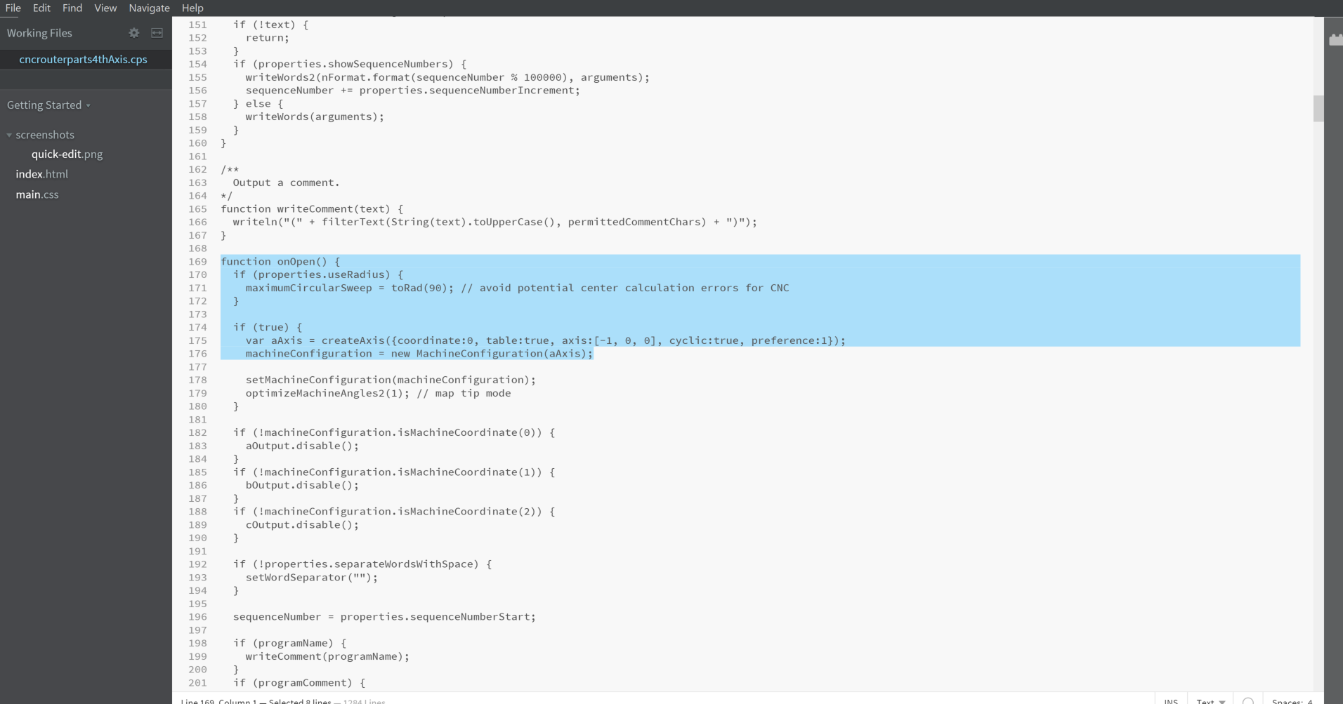
Once you have it opened, search for “Function onOpen” and look for the line
if (false) {
var aAxis = createAxis({coordinate:0, table:true, axis:[-1, 0, 0], cyclic:true, preference:1});
machineConfiguration = new MachineConfiguration(aAxis);
Change if (false) to if (true).
Next Search for “var tcp”
var tcp = true;
if (tcp) {
setRotation(W); // TCP mode
Change var tcp = true to var tcp = false;
That is it. I saved this as another post processor instead of overwriting the original. I am pretty sure that if you overwrite the original, it will not choose to post process the A axis unless the CAM refers to a rotary axis. I have not tested this and it is easy enough to switch between them and if you forget, it will be obvious that it did not work anyway.
This is the end of what I have done so far. I am building the frame setup for mounting this. It will not be permanent, but will be able to use 4 feet of cutting space on the X axis. The setup I have designed does limit my maximum stock size to 8 inches. But having 4 feet to work within was my goal. Table legs and banisters are on the list. Otherwise I would have mounted it under the table and had the cutter reach through. But that is far to limiting in size. Maybe I will do that in the future, or maybe I will try to make it 8 foot with another mounting setup. I will link out to my Fusion design of the mounting and the CAM I used to set up registers on the table when I confirm everything working. Once I post some actual code and turn something, I will add some more. Hopefully this, along with some of the links I have thrown out there of the 2 people with the CNCRP machines that have posted anything, will get you going.
Please add any information that you have if you do. What did you figure out that can help the rest of us?


Leave a comment